Welding Reference Information for Designers and Welders of Aluminum Ultra High Vacuum (UHV) Chambers
Aluminum UHV Weld Design
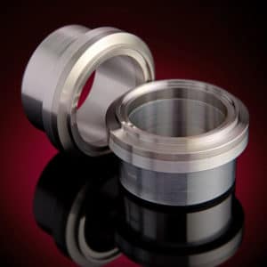
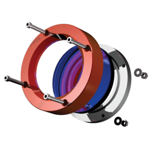
Most facilities familiar with Ultra High Vacuum (UHV) have experience welding stainless steel to UHV standards; however, many have not had occasion to weld aluminum to UHV standards. We offer this brief guide for designing and welding aluminum and Atlas Technologies’ aluminum – stainless bimetallic Atlas Flanges and Atlas Bimetallic Transitions to ultra high vacuum (UHV) standards.
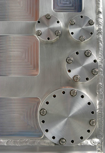
Similar Masses: We try to design weld geometries that have similar masses when ever possible. If there is a large difference between the mass of the chamber and the mass of a flange for example, this can cause frustration because the more massive chamber will tend to be cooler than the less massive flange and the flange will preferentially melt. If similar masses are not a possibility often times thermal chokes can be machined into the massive part, which constrain the heat loss. Also burying the less massive chamber in the massive flange will tend to spread the heat about in a more uniform manner.
It is very often convenient to have V-grooves machined into aluminum weld joints. This permits liberal use of filler rod which reduces cracking. If joining tubes the V grooves should be on the inside of the tube and penetrate ~2/3 the thickness of the wall.
Cleanliness: Cleanliness is very important when welding aluminum. Make sure that the weld surfaces including the filler rods are freshly cleaned and fully dried. Even though aluminum forms an oxide instantaneously in air a freshly cleaned surface with scotch bite can reduce the thickness and contamination present in that oxide. This is important because Aluminum melts between 580-650 C however its oxide melts at ~1760+C and is heavier than the aluminum alloy. Because of this, the oxide crust can sink into the molten weld and be a source of porosity.
Preheating the Aluminum: Because aluminum is such an excellent thermal conductor vast amounts of heat are required when beginning a weld. As this heat spreads ahead of the weld bead it accumulates in the part. This tends to reduce the amount of required heat during a weld. Rather than stopping and starting which are often areas for leaks, we recommend using a foot pedal current controller.
During welding, stainless steel will glow red at its welding temperature, aluminum however will not, it will melt before it will glow. The welder must observe the melted weld puddle rather than the glow.
Aluminum TIG Welding for UHV and Aluminum Atlas Flanges, Bimetallic Transitions Coupling and Fittings
Welding Thick Aluminum for Vacuum
Greater than 6mm + Thick (¼”) :
Flange to Chamber, us Atlas Face Mount FM Flanges
Atlas Technologies’ UHV Bond
Max Bond Temp: Temperature at the bond should not exceed 300 C . Keep a
damp rag on the joint to prevent over heating during welding
Mode: DC (AC can often be used to clean the oxides)
Gas:
Pure Helium (no Argon used)
Use Gas Lens
Gas Flow:
35 – 40+ cfm
Tip:
2.38mm (3/32″) 2% Thoriated Tungsten (W)
Sharpen tip to a short blunt taper, too sharp a tip will drill holes in the aluminum
Filler Rod:
4043 1/16″ (1.58mm)
Use 5356 if the parts are to be anodized
Amperage:
125 –200 Amps controlled by the foot pedal
Porosity:
If the W sputters into the weld or is dipped in the weld it can form porosity
Appearance of Weld:
The weld area will form a black soot cover with a bright metallic center. This can be cleaned off with scotch bright or a stainless steel wire brush after the welding.
If a yellow discoloration forms on the weld it is a result of Oxygen contamination in the Helium.
Welding Thin Aluminum for Vacuum
Less than 6mm + Thick (¼”) :
Tube to Tube, Atlas Weld Neck (WN) Flanges
Atlas Technologies’ UHV Bond
Max Bond Temp: Temperature at the bond should not exceed 300 C . Keep a
damp rag on the joint to prevent over heating during welding.
Mode: AC
Gas:
Argon, In thicker sections add a small amount of helium
Use Gas Lens
Gas Flow:
15 cfm
Tip:
2.38mm (3/32″) Pure Tungsten (W)
Sharpen tip to a short blunt taper, too sharp a tip will drill holes in the aluminum
Filler Rod:
4043 1/16″ (1.58mm)
Use 5356 if the parts are to be anodized
Amperage:
75 –125 Amps controlled by the foot pedal
Porosity:
If the W sputters into the weld or is dipped in the weld it can form porosity
Appearance of Weld:
The weld will be bright metallic with no soot. If a yellow discoloration forms on the weld it is a result of Oxygen contamination of the Helium.


